

DIY: Repair Shelly 2.5 Switch
Shelly – Home control for nerds
Many of you know them, the Shelly Switches. Shelly is one of the fastest growing IoT brands and manufactures a wide range of programmable IoT devices.
I myself use various Shelly 2.5, small smart 2-channel WiFi switches with integrated current/power measurement, which can be installed directly in flush-mounted sockets in addition to switches, sockets etc.. I have installed dozens of these switches in my house and use them to control lights, sockets and appliances. The Shelly switches are based on a and are freely programmable. They can be loaded with the firmware, for example.
The Shelly Switches can be perfectly integrated into the and controlled with Alexa or other voice assistants.
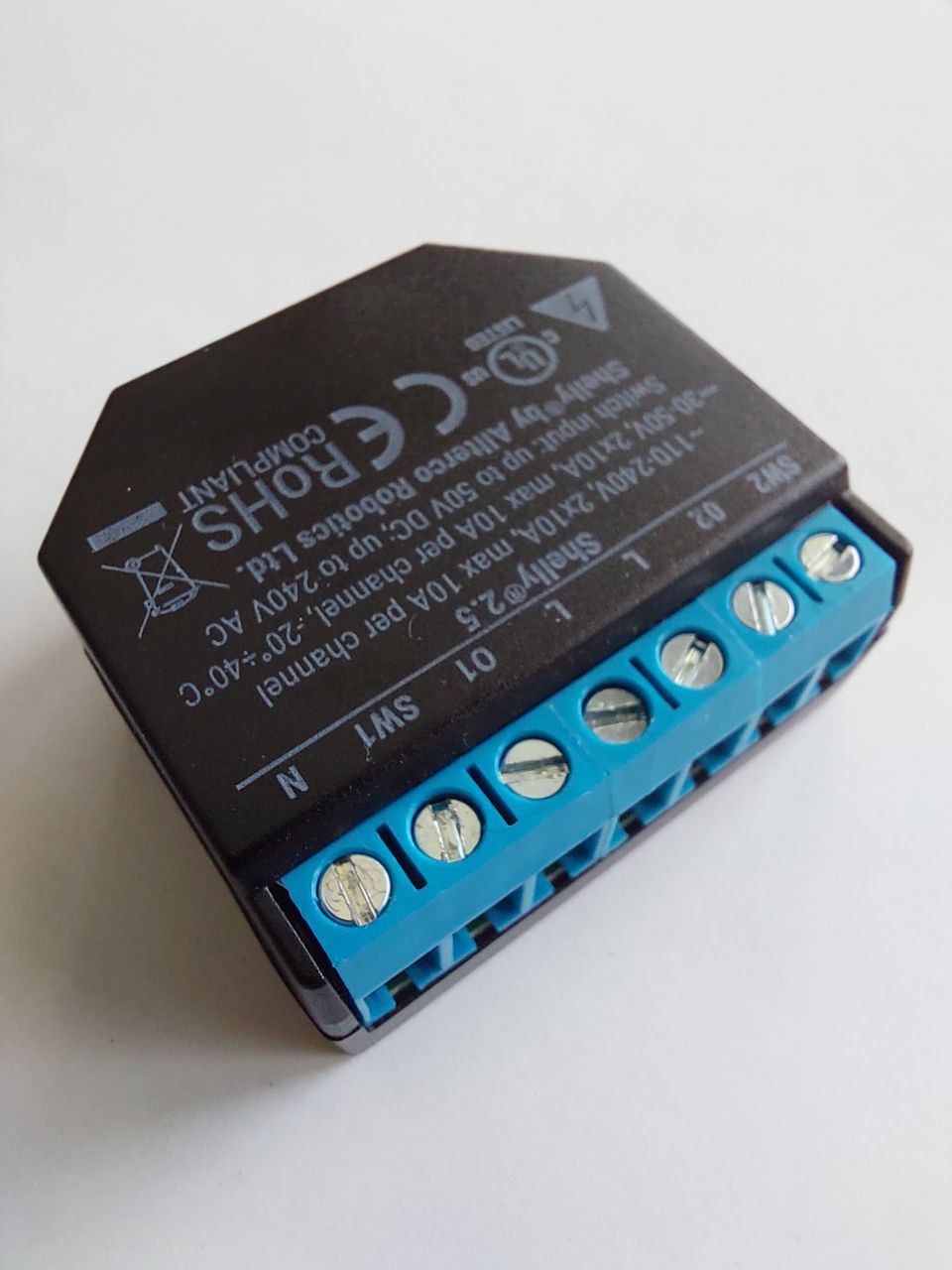
Here is such a Shelly 2.5 WiFi switch for installation in flush-mounted boxes
But unfortunately the Shellys have a problem…
Noise is the death of Shelly
I have been using the Shellys for almost four years now, but four of them have already failed in the meantime.
The problem: A dried-out capacitor, or more precisely an electrolytic capacitor.
Unfortunately, the problem is homemade. The design of the Shelly switches is extremely compact. And because they are used directly in the flush-mounted box, the switches can certainly heat up. The electrolytic capacitors that break here are 100µF / 16V standard types, without an extended temperature range. This can lead to the electrolyte in the electrolytic capacitors drying out, which reduces the capacitance of the electrolytic capacitor. Until the electrolytic capacitor loses its function and the Shelly fails as a result. The problem is also known as and affected a number of electronics from the Far East around the turn of the millennium.
Incidentally, the problem manifests itself even before the final failure of the switches through a clearly audible noise. So listen to your walls to see if your shellies are hissing…
Fortunately, the Shelly Switches are easy to repair. Below is an illustrated step-by-step guide. Exemplary for the Shelly 2.5, but the problem probably also affects other Shelly IoT devices and is similarly applicable there.
Step 1: Remove and open
First you have to remove the affected Shelly.
ATTENTION: Shelly switches are usually integrated into the 230V mains supply. You are therefore working with mains voltage. Always remember the 5 most important safety rules:
- Switch off
- Secure against restarting
- Determine absence of voltage
- Earthing and short-circuiting
- Cover or cordon off neighboring live parts
Mains voltage is life-threatening. If in doubt, have the work carried out by an electrician!
Once you have removed the Shelly, you need to open it. The housing has a small notch, here you can easily lever the two halves of the housing apart with a screwdriver. Be careful not to damage the housing!
The WiFi antenna is glued into the upper housing cover and connected to the circuit board with a tiny pigtail connector. Make sure to carefully detach the antenna from the pigtail or better just leave it on.
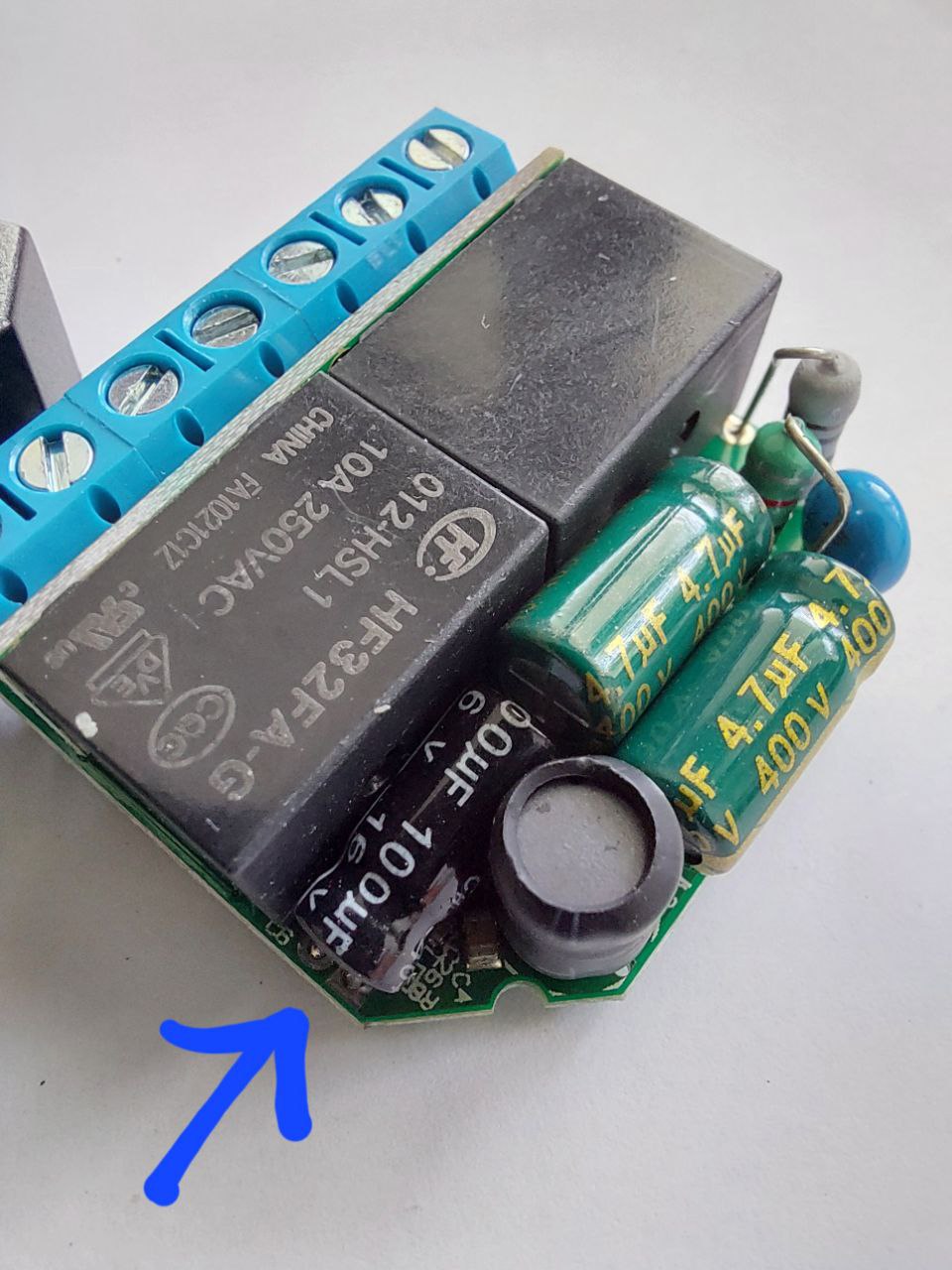
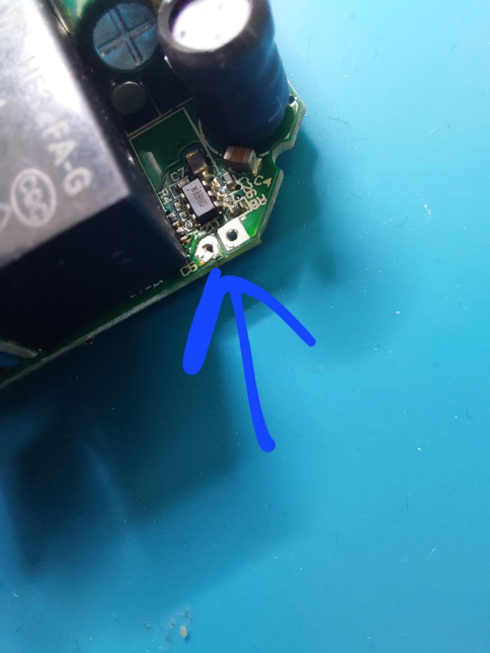
The picture shows the opened Shelly 2.5. The arrow points to the defective capacitor.
This capacitor must be desoldered and replaced with a new 100µF / 16V electrolytic capacitor. Make sure you buy exactly the same type and pay particular attention to the size. Space is extremely limited in the housing. If you can get a type with a higher temperature resistance, use this one.
ATTENTION: Make sure you note the correct polarity of the electrolytic capacitor!
Step 2: Desolder defective electrolytic capacitor
To desolder the electrolytic capacitor, I first cut the connection wires of the electrolytic capacitor and then desoldered the two wire ends individually.
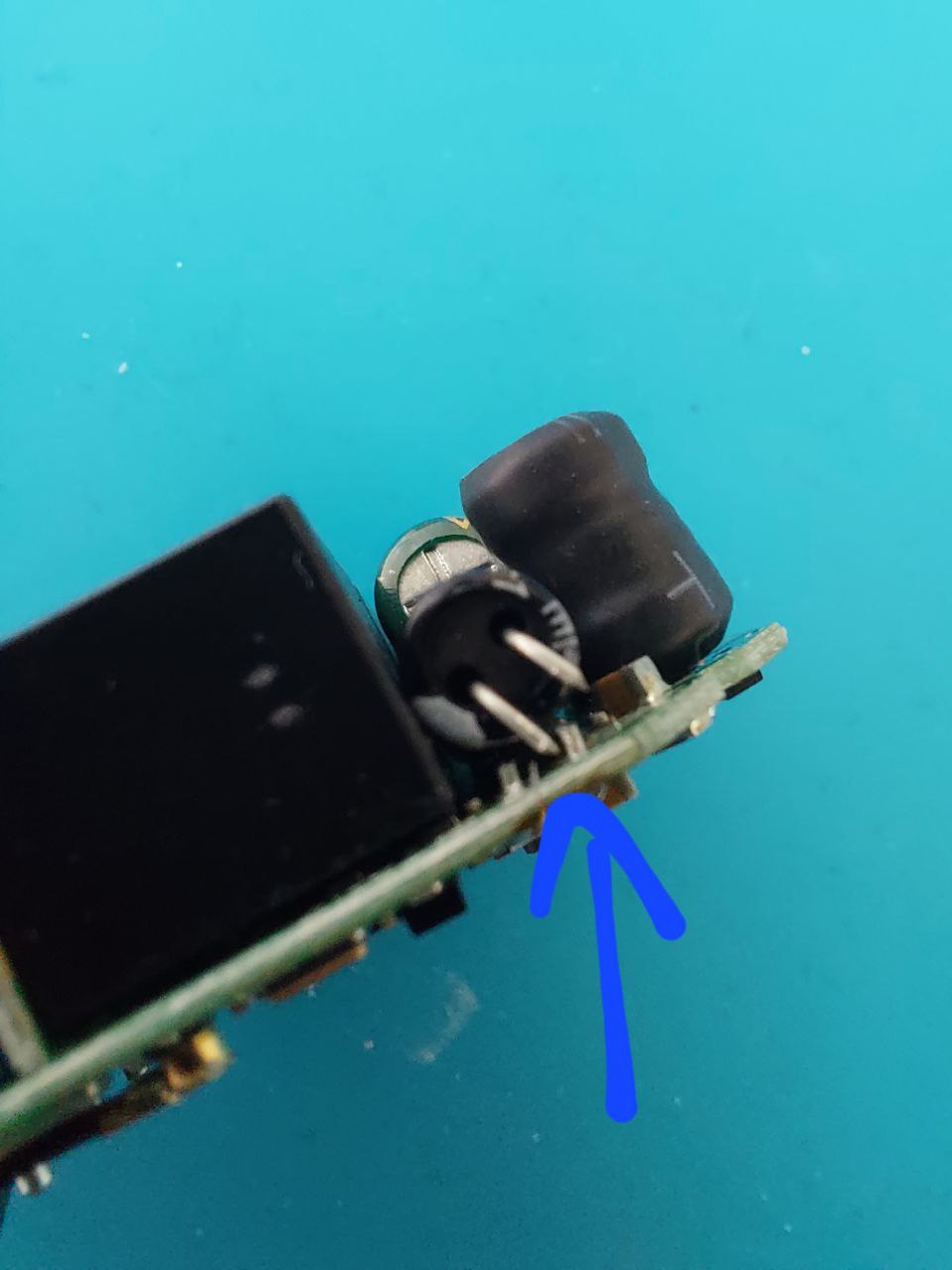
Here you can see the cut connection wires of the electrolytic capacitor.
Now turn the circuit board over. The following picture shows the two soldering points where the wires of the electrolytic capacitor are soldered.
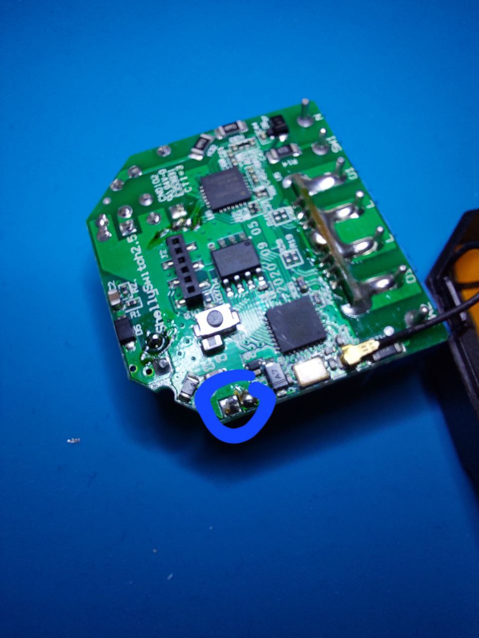
Solder pads of the electrolytic capacitor.
Now solder the wires one after the other. I recommend using a good flux, a solder suction pump and desoldering braid to get the hole really clean.
Solder pads with clean hole, after desoldering the electrolytic capacitor
Personal tip: I use flux and make the solder liquid on the pads and then blow vigorously. This usually works better than the desoldering suction pump. But don’t burn yourself in the process!
Step 3: Solder in a new electrolytic capacitor
Now solder in the new electrolytic capacitor in the correct orientation / polarity. The marked minus pole must point to the relay!
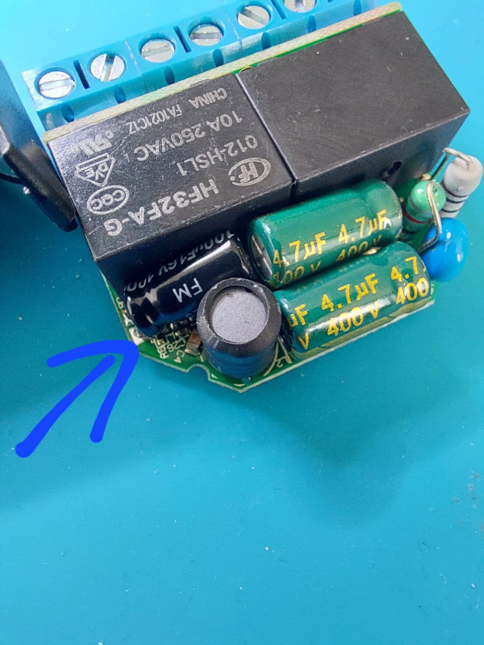
Shelly 2.5 with newly soldered-in electrolytic capacitor.
Step 4: Reassemble everything
Now put everything back into the housing. First place the circuit board in the top shell and lay the antenna cable through the cut-out. The whole thing should now look like this:
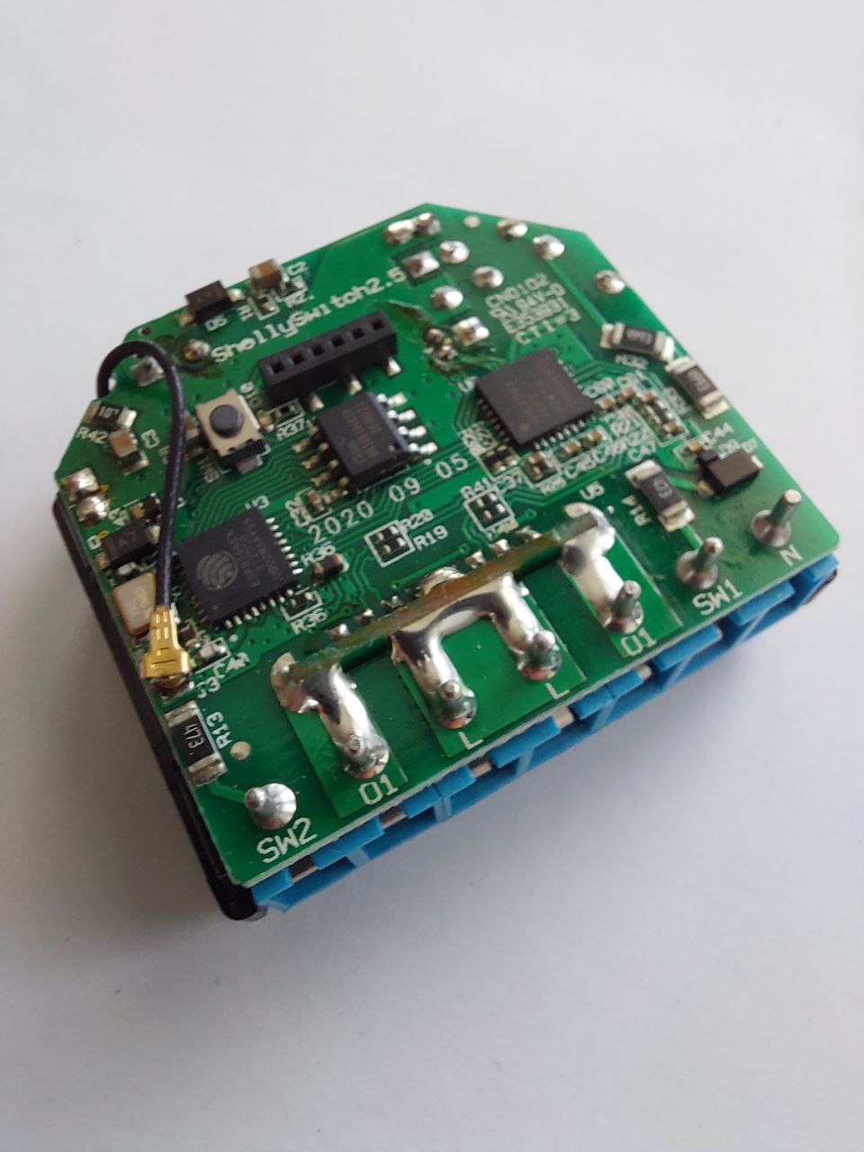
The Shelly half assembled.
Now close the housing and you’re done!
Step 5: Test function
Next, you should test the function of the Shelly. You can also do this with a laboratory power supply unit without connecting the Shelly to the mains.
The good thing is that the Shelly retains its programming and configuration when it is repaired. So you don’t have to set it up again after you have repaired it. You can operate it on the laboratory power supply with 24V – 60V.
Attention: In this case, VCC / 24V must be connected to the N connection and the ground to the L connection!
The diagram below shows the correct wiring on the laboratory power supply unit.
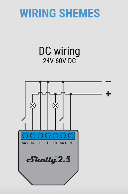
DC wiring on the laboratory power supply unit
The Shelly should now log back into the configured network and function normally. You can of course also use the reset test for a few seconds to restart the Shelly in access point mode and reconfigure it.